
西门子 6ES7131-4BB01-0AB0 西门子 6ES7131-4BB01-0AB0 西门子 6ES7131-4BB01-0AB0

SIMATIC DP,5 个电子模块 用于 ET 200S,2 DI High Feature 24V DC,15mm 结构宽度 带可设置参数的输入端延时 编码器短路诊断 利用 LED 集中报错(集中报错) 5 件/包装单位
|
建议同时购买:
*** 备件 *** SIMATIC ET 200SP, 数字输出模块, 数字输出 16个 24V DC/0.5A 标准型, 适合用于 A0 类型的基座单元, 颜色代码 CC00, 模块诊断

SIMATIC DP,电子模块 2 AI I High Feature 用于 ET 200S,15mm 结构宽度, 每模块的循环时间:0.5ms, +/-20mA;15 位+符号位, 4.. 20mA;15 位, 操作限值 +/-0.1% 利用 LED 集中报错(集中报错)

SIMATIC DP,IM151-8 PN/DP CPU 针对 ET200S, 192 KB 主存储器, 内部的 PROFINET 接口 (带三个 RJ45 端口) 作为输入输出控制器,不带电池 需要有 MMC
|
|||||||||||||||||||||||||||||||||||||||||||||||||||||||||||||||||||||||||||||||||||||||||||||||||||||
问题1:S7-200 CPU内部存储区类型?
回答:S7-200 CPU内部存储区分为易失性的RAM存储区和永久保持的EEPROM两种,其中RAM包含CPU工作存储区和数据区域中的V数据存储区、M数据存储区、T(定时器)区和C(计数器)区,EEPROM包含程序存储区、V数据存储区的全部和M数据存储区的前14个字节。
也就是说V区和MB0-MB13这些区域都有对应的EEPROM永久保持区域。
EEPROM的写操作次数是有限制的(最少10万次,典型值为100万次),所以请注意只在必要时才进行保存操作。否则,EEPROM可能会失效,从而引起CPU故障。
EEPROM的写入次数如果超过限制之后,该CPU即不能使用了,需要整体更换CPU,不能够只更换CPU内EEPROM,西门子不提供这项服务。
问题2:S7-200 CPU的存储卡的作用?
回答:S7-200还提供三种类型的存储卡用于永久存储程序,数据块,系统块,数据记录(归档)、配方数据,以及一些其他文件等,这些存储卡不能用于实时存储数据,只能通过PLC—存储卡编程的方法将程序块/数据块/系统块的初始设置存于存储卡内。
存储卡分为两种,根据大小共有三个型号。
32K存储卡:仅用于储存和传递程序、数据块和强制值。32K存储卡只可以用于向新版(23版)CPU传递程序,新版CPU不能向32K存储卡中写入任何数据。而且32K存储卡不支持存储程序以外的其他功能。订货号:6ES7 291-8GE20-0XA0。
64K/256K存储卡:可用于新版CPU(23版)保存程序、数据块和强制值、配方、数据记录和其他文件(如项目文件、图片等)。64K/256K新存储卡只能用于新版CPU(23版)。64K存储卡订货号: 6ES7 291-8GF23-0XA0;256K存储卡订货号:6ES7 291-8GH23-0XA0。
为了把存储卡中的程序送到CPU中,必须先插入存储卡,然后给CPU上电,程序和数据将自动复制到RAM及EEPROM中。
存储卡的使用完整限制条件,请参考《S7-200系统手册》附录A 技术规范—可选卡件一节。
S7-200的外部存储卡有哪些功能?
459464
问题3:S7-200 CPU内的程序是否具有掉电保持特性?
回答:S7-200 CPU内的程序块下载时,会同时下载到EEPROM中,也就是说程序下载后,将永久保持。同样,系统块和数据块下载时,也会同时下载到EEPROM中。
问题4:S7-200 CPU内部的数据的掉电保持特性?
回答:S7-200系统手册第四章——“PLC基本概念”一章中“理解S7--200如何保存和存储数据”一节详细介绍了S7-200 CPU内数据的掉电保持特性,建议用户仔细阅读。
S7-200 CPU内的数据分为RAM区和EEPROM区。
其中,RAM区数据需要CPU内置的超级电容或者外插电池卡才能实现掉电保持特性。
对于CPU221和CPU222的内置超级电容,能提供典型值约50小时的数据保持。
对于CPU224,CPU224XP,CPU224XPsi和CPU226的内置超级电容,能提供典型值约100小时的数据保持。
超级电容需要在CPU上电时充电。为达到上述指标的数据保持时间,需要连续充电至少24小时。
当该时间不够时,可以购买电池卡,以获得更长时间的数据保持时间。
EEPROM区能实现数据永久保持,不依靠超级电容或者电池就可以保持数据。
问题5:S7-200 CPU内部数据的工作顺序?
回答:S7-200 CPU一上电后,CPU先去检查RAM区域中的数据,如果在超级电容或者电池有电的情况下,数据并未丢失,则使用该RAM区的数据;如果超级电容或者电池没电了,导致数据丢失,则CPU去读EEPROM中相应的区域(包含数据块中的数据定义内容),如果在EEPROM中存有永久保持的数据,则CPU将EEPROM中的数据写回到RAM区中,再进行下面的工作。
如果EEPROM中也没有对应存储区的数据了,则该存储区的数据将变成0。
问题6:S7-200 CPU电池卡的使用注意事项?
回答:新版S7-200 CPU电池卡有两种型号。
对于CPU221和CPU222,由于其中没有实时时钟,则对应的为时钟电池卡,订货号为:6ES7297--1AA23--0XA0。
对于CPU224,CPU224XP,CPU224XPsi和CPU226,电池卡仅提供电池功能,订货号为:6ES7 291--8BA20--0XA0,该款电池卡型号又叫做BC293。
电池卡的寿命典型值约为200天,当插上电池卡后,如果CPU处于工作状态或者超级电容有电的情况下,并不消耗电池卡的电量。当电池卡的电量消耗完毕之后,该电池卡就报废了。
S7-200电池卡不能充电,使用完毕就不能再用了,只能购买新的电池卡了。
S7-200没有检测电池卡内剩余电量的状态位和这种功能。
新版S7-200 CPU电池卡不能用于老CPU,即订货号为6ES7xxx-xxx21-0XB0和6ES7xxx-xxx22-0XB0以及更老版本的CPU。

图1
以上为两种电池卡以及所在插槽位置。
电池卡的使用完整限制条件,请参考《S7-200系统手册》附录A 技术规范—可选卡件一节。
问题7:S7-200 CPU内EEPROM的使用方法?
回答:EEPROM的写入分为如下几种情况:
1、MB0—MB13的设置,只需要在系统块—断电数据保持中设置即可。
默认情况下,系统块设置如下图蓝框中所示,即MB14—MB31,这些区域没有对应的EEPROM区域,无须考虑EEPROM写入次数限制。

图2
MB0—MB13如果在系统块中设置成掉电保持区域,如图2红框中所示,并将系统块下载到CPU之后,则这14个字节的数据在掉电的瞬间会将数值写入EEPROM中,如果掉电时间超过超级电容和电池的保持时间之后,再上电时,CPU会将EEPROM中存储的数据数值写回到RAM中对应的存储区,实现永久保持数据的目的。
注意:实现该功能一定要将修改过的系统块下载到CPU中。
2、数据块中定义的数据,如图3所示,当下载数据块的时候,同时会将定义的数据下载到EEPROM中,这样,当掉电时间超过超级电容和电池的保持时间之后,再上电时,CPU会将EEPROM中存储的数据块中定义的数据数值写回到RAM中对应的存储区,实现永久保持数据的目的。也就是恢复成数据的初始设置值。
注意:实现该功能一定要将定义好数据的数据块下载到CPU中。

图3
3、使用SMB31和SMW32控制字来实现将V区的数据存到EEPROM中
特殊存储器字节31 (SMB31)命令S7-200将V存储区中的某个值复制到永久存储器的V存储区,置位SM31.7提供了初始化存储操作的命令。特殊存储器字32 (SMW32)中存储所要复制数据的地址。如图4为S7-200系统手册内关于SMB31和SMW32的使用说明。

图4
采用下列步骤来保存或者写入V存储区中的一个特定数值:
1. 将要保存的V存储器的地址装载到SMW32中。
2. 将数据长度装载入SM31.0和SM31.1。具体含义如图4所示。
3. 将SM31.7置为1。

图5
注意:如果在数据块中定义了某地址的数据,而又使用这种办法存储同样地址的数据,则当CPU内超级电容或电池没电时,CPU再上电时将采用SMB31和SMW32存储的数据。
问题8:EEPROM写入次数的统计?
回答:每次下载程序块/数据块/系统块或者执行一次SMB31.7置位的操作都算作对EEPROM的一次写操作,所以请注意在程序中一定不要每周期都调用SMB31/SMW32用于将数据写入EEPROM内,否则CPU将很快报废。
问题9:不使用数据块的方法,如何在程序中实现不止一个V区数据的存储?
回答:由于SMB31/SMW32一次最多只能送入一个V区双字给EEPROM区域,因而当有超过一个双字的数据需要送入EEPROM中时,需要程序配合实现。具体操作方法可参照如下的例子,即使用SMB31/SMW32送完一个数据(字节/字/双字)之后,通过一个标志位(如M0.0)来触发下一个SMB31/SMW32操作,之后需要将上一个标志位清零,以用于下一次的存储数据的操作。


由于SM31.7在每次操作结束之后都自动复位,因而不能使用它作为第二次触发操作的条件。
以上程序仅供参考。
或者可以参考如下FAQ,多次调用指令库用以存储多个V区变量到EEPROM存储区中:
如何在 CPU 内部 EEPROM 存储空间中永久保存变量区域?
17471561
问题10:定时器和计数器以及MB14-MB31的掉电保持性能?
回答:计数器和TONR型的定时器(T0-T31,T64-T95)能够实现掉电保持。这些区域只能由超级电容和电池来进行数据的掉电保持,他们并没有对应的EEPROM永久保持存储区。当超过超级电容和电池供电的时间之后,这些计数器和TONR定时器的数据全部清零。
TON和TOF型的定时器(T32-T63,T96-T255)没有掉电保持数据的功能。请不要在系统块中设置这些区域为掉电保持,如图6所示为错误做法:
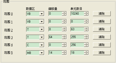
图6
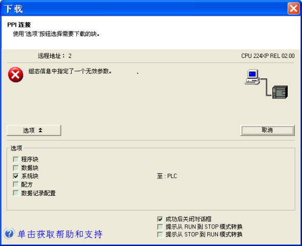
按上述做法设置之后,下载系统块时会导致如下错误发生:
. TDC IE communication introduction
TDC system is the newest digital control system of SIMADYN D family and it has the highest quality in the SIMATIC control system family.
As one part of TIA family it has powerful communication function. The system provides the MPI communication protocol, Profibus communication protocol, Ethernet communication protocol. It is easy to communicate with other simatic product, for example S7-300, S7-400, HMI and drives product.
For Ethernet communication, the hardware platbbbb is CP51M1 which supply a standard RJ45 Ethernet interface; the old interface CP5100 is discontinued as per Aug. 1 2005.
For communication task, system can exchange process data with other TDC system or PLC S7 system through CP51M1 module.
For communication protocol, TDC system supplies TCP/IP protocol and/or UDP protocol.
For transfer modes, refresh mode, handshake mode, multiple mode and select mode are available for selection.
For net speed it can work with 10Mbit and 100Mbit network, the module can automatically sense the net speed.
2. TDC configuration steps
2.1 Hardware configuration in SIMATIC Manager
2.1.1 Create a new S7 project
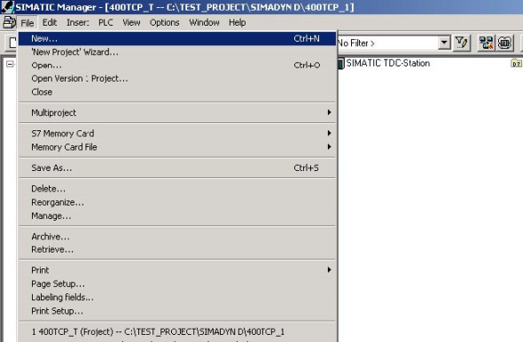
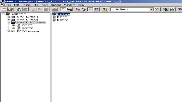
2.1.2 Insert a TDC station

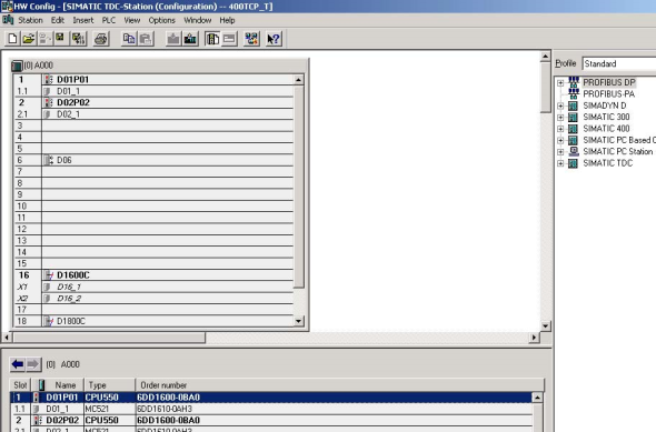
2.1.3 Select hardware configuration in SIMATIC Manager, double click to open it
2.1.4 Insert the subrack, CPU, communication board CP51M1 and other module from the hardware catalog
Keep the same type with which is used in the sub rack.
2.1.5 Define the CPU module and communication module properties
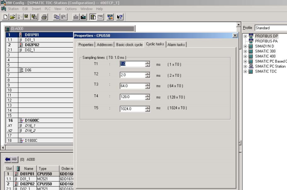
For CP51M1, we need to define the module name firstly

For Ethernet property we need to define the IP address and subnet mask

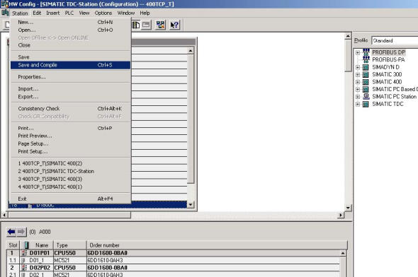
2.1.6 Save and compiled the hardware configuration
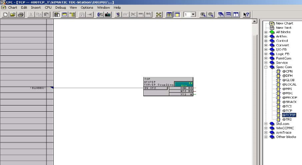
2.2 CFC programming
2.2.1 Insert a CFC program in SIMATIC Manager, double click it to open it
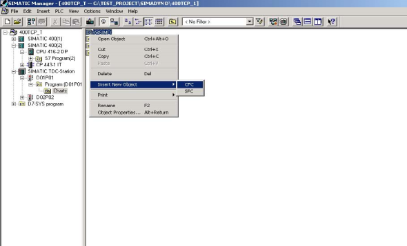
2.2.2 Insert the TCPIP communication block into the chart, define the connection address which is set in the hardware configuration and select the proper cycle time
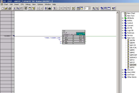
2.2.3 Insert the send function block CTV_P, define the connection:
| CTS | P51M1 hardware address which is set in hardware configuration | |||||||
| AT |
channel name.protocol type–CP51M1 port number.partner IP address–partner port number, for example: 'TRAN.T-02004.192168000003-02002’ |
|||||||
| MOD | normally we select handshake mode | |||||||
| EN | set to 1 to enable the FB | |||||||
| NBY | define the bbbegram length in bytes | |||||||
2.2.4 Insert the DWR_D block to write the communication content to the communication buffer
Here we can define the offset in the communication buffer by set connector1/2. The final result is the sum of offset1 and offset2.
For connector SWP we set it to 1 if it communicates with a PLC.
The data we try to send is set in connector X, here is 44 as an example.

For receive part, we can do it in the same way.
For connector AR of CRV_P, we do not need to define the partner IP address–partner port number.
2.2.5 Compiled the program and download it to the memory card and restart the system
3. S7-400 configuration steps
3.1 S7 hardware configuration
First insert the S7-400 station, and then open the hardware configuration to insert the modules which are available on the sub rack.
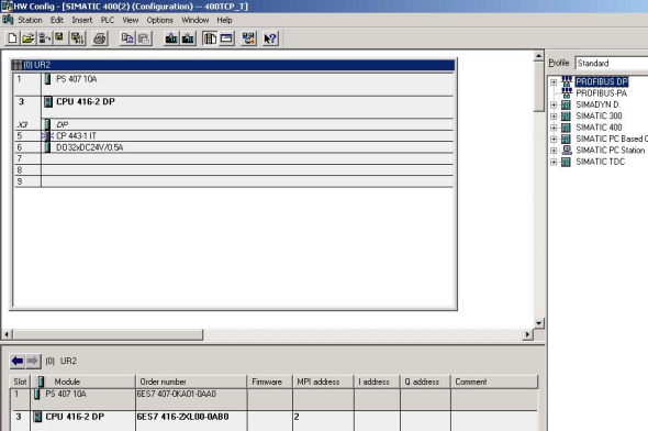
For CP443-1 module we need to define the IP address and subnet mask.
The IP address will be used in the CFC program.
3.2 network configuration in the Netpro software
Open Netpro under hardware configuration menu

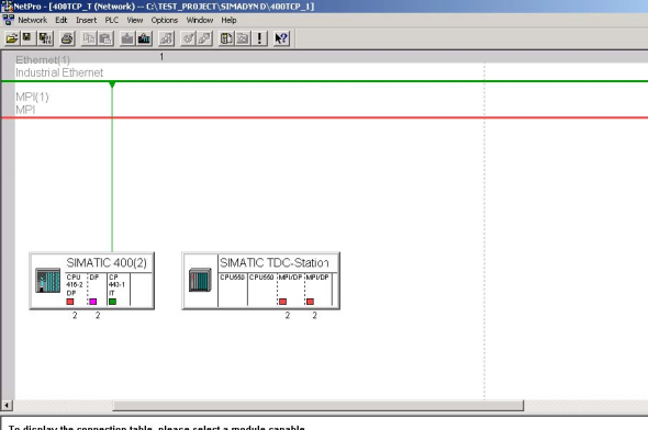
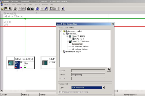
Select the CPU in the SIMATIC station and insert a new connection,
Select unspecified station and
TCP connection, press apply button.
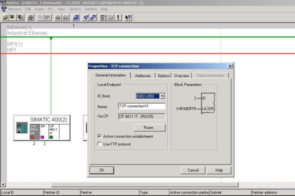
Select the ID number, record the address LADDR.
Both of them will be used in the S7 program.
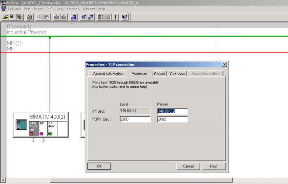
Under address menu we need to set the local port number, partner address and port number, press OK button to confirm the setting.
For other connection you need, you can do it in the same way.
Then we need to save and compile the configuration.
We need to download not only the hardware configuration, but also the Netpro configuration to the CPU.

3.3 Programming in the S7 CPU

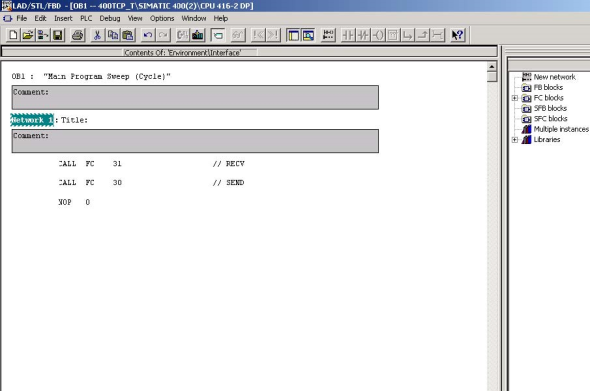
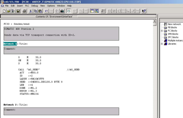
For the industrial Ethernet communication we use the FC5 AG_SEND, FC6 AG_RECV block.
These blocks transfer and receive the data on the configured TCP connection to and from the Ethernet CP.
Here we made two FC separabbby for send and receive function, one is FC 30 for FC5, and another is FC31 for FC6.
For FC5, we need to define:
| ACT: | set it to one to trigger FC | ||||||
| ID: | connection ID number which is set in Netpro | ||||||
| LADDR: | CP module start address which is set in hardware configuration, also | ||||||
| available in Netpro. The address is in HEX mode, for example 3FF8H | |||||||
| SEND: | set the transfer data address and buffer length | ||||||
| keep the bbbbat for example P#DB31.DBX100.0 BYTE 8 | |||||||
| LEN: | numbers of bytes to be send from the transport data area with this job | ||||||
| DONE: | bit signal for executed status | ||||||
For error bbbbuate we can check the connector Error and Status. For the status code we can get detail inbbbbation in the FC5 debbbbbbion documentation.
For FC6, we can do it in the same way.
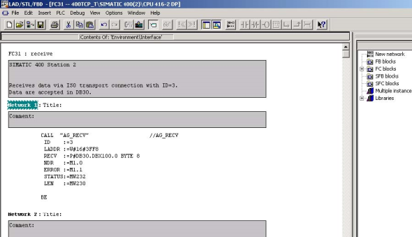
Because we use DB30 and DB31 in the program FC30 and FC 31, we must insert these two data block and download it to the CPU.
4. Physical connection
TDC side: CP51M1 supply RJ45 interface
S7 side: CP443-1 supply RJ45 interface
Between the double sides we need a Switch to connect.
西门子 6ES7131-4BB01-0AB0 西门子 6ES7131-4BB01-0AB0 西门子 6ES7131-4BB01-0AB0


